Laser cutting of technical ceramics
Ceramic laser cutting is the use of high energy density laser beam irradiation of ceramic materials, so that the ceramic material in a very short period of time to rapidly melt, vaporize or evaporate, so as to achieve the cutting of ceramic materials. It has the advantages of good cutting quality, high cutting efficiency, small heat-affected zone, etc. It is suitable for processing complex graphics and curves, and can realize mass production.
Ceramic Laser Cutting Principle
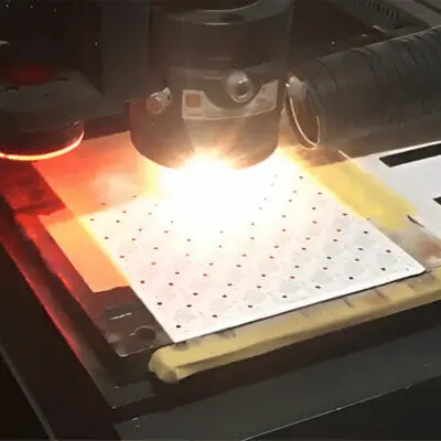
The principle of ceramic laser cutting utilizes the interaction between the laser beam and the ceramic material. When the laser beam irradiates the surface of the ceramic material, a high-temperature, high-pressure melting zone is formed on the surface of the ceramic material. Due to the high energy density of the laser beam, the melting zone evaporates rapidly in a very short period of time, thus enabling the cutting of the ceramic material.
Customized ceramic laser cutting
Ceramic laser cutting can process complex patterns, penetration slots and holes, as well as pre-treated demarcation lines for breaking on ceramic substrates. In addition, we can provide customized processing services according to customers' technical requirements and drawings.

Aluminum oxide substrate laser cut groove

Laser Cutting of Aluminum Nitride Substrates

Laser Cutting of Aluminum Nitride Substrates

AlN Insulating Gasket

Laser cut insulating shims

Aluminum oxide substrate laser cutting
Ceramic Laser Processing Capabilities
- Maximum processing range: 250×250mm
- Maximum processing thickness: 2.0 (AL)2O3), 3.0 (ALN), 1.0 (ZrO2),
- Minimum hole diameter: 0.02mm
- Minimum distance between hole and edge: 0.2mm
Laser Cutting Tolerance Reference List
The following table is for reference only. Usually, we will make the products according to the drawings provided by customers.
| sports event | Ceramic Laser Cutting | ||
| routine | accurate | ||
| Length Tolerance | T≤0.645 | +0.20/-0.05 | +0.15/-0.05 |
| 0.635<t ≤ 1.0 | +0.25/-0.10 | +0.20/-0.05 | |
| 1.0 | +0.30/-0.10 | +0.25/-0.10 | |
| Thickness Tolerance | ±10% Minimum: ±0.05 | ±7% Minimum: ±0.05 | |
| Tolerance of distance between capture lines or holes | ±0.05 | ±0.05 | |
| Hole Diameter Tolerance | T≤0.645 | ±0.075 | ±0.05 |
| T>0.635 | ±0.1 | ±0.075 | |
| Tolerance of distance from edge to catch line or hole | T≤0.645 | +0.15/-0.05 | +0.15/-0.05 |
| 0.635<t ≤ 1.0 | +0.20/-0.05 | +0.20/-0.05 | |
| 1.0 | +0.25/-0.10 | +0.25/-0.10 | |
| Overall camber | 0.3% Minimum: 0.05 | 0.25% Minimum: 0.05 | |
| Parallelism/Perpendicularity | 0.3% Longest Edge Size | 0.2% Longest Edge Size | |
